
Nugroho , Sapto (2002) Rancang bangun penguat daya RF. Undergraduate thesis, FMIPA UNDIP.
![[img]](/style/images/fileicons/application_pdf.png) | PDF Restricted to Repository staff only 3793Kb | |
| PDF 15Kb | |
| PDF 350Kb | |
| PDF 710Kb | |
| PDF 412Kb | |
| PDF 1051Kb | |
| PDF 413Kb | |
| PDF Restricted to Repository staff only 983Kb | |
| PDF 341Kb | |
| PDF 345Kb | |
| PDF 1119Kb |


Abstract
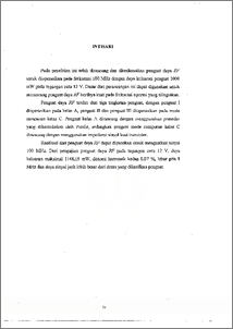
Pada penelitian ini telah dirancang dan direalisasikan penguat daya RF untuk dioperasikan pada frekuensi 100 MHz dengan daya keluaran penguat 1000 mW pada tegangan catu 12 V. Dasar dari perancangan ini dapat digunakan untuk merancang penguat daya RF berdaya kuat pada frekuensi operasi yang diinginkan. Penguat daya RF terdiri dari tiga tingkatan penguat, dengan penguat dioperasikan pada kelas A, penguat II dan penguat III dioperasikan pada mode campuran kelas C. Penguat kelas A dirancang dengan menggunakan prosedur yang dikemukakan oleh Purdie, sedangkan penguat mode campuran kelas C dirancang dengan menggunakan impedansi sinyal kuat transistor. Realisasi dari penguat daya RF dapat digunakan untuk menguatkan sinyal 100 MHz. Dari pengujian penguat daya RF pada tegangan catu 12 V, daya keluaran maksimal 1148,15 mW, distorsi harmonik kedua 0,07 %, lebar pita 8 MHz dan daya sinyal jauh lebih besar dari derau yang dihasilkan penguat. The RF power amplifier has been designed and realized to operate at the frequency of 100 MHz with 1000 mW of power output at 12 V supply voltage in this research. Based on this design, it will be used to design of the RF power .amplifier with large output power at desired frequency operation. The RF power amplifier consist of three stages amplification, with first amplifier is operated in class A, second and third amplifier are operated in fixture mode class C. Class A amplifier is designed with using the procedure that presented by Purdie; while fixture mode class C amplifier is designed by using of large signal transistor impedance. Realizing of the RF power amplifier can be able to used for amplifying signal of 100 MHz The measurement of the RF power amplifier at 12 V supply voltage; maximal output power of 1148,15 mW; second harmonic distortion of . 0,07 %; bandwidth 8 MHz and signal power are larger then noise that generated This document is Undip Institutional Repository Collection. The author(s) or copyright owner(s) agree that UNDIP-IR may, without changing the content, translate the submission to any medium or format for the purpose of preservation. Theivthor(s) or copyright owner(s) also agree that UNDIP-IR may keep more than one copy of this submission for purposes of security, back-up and preservation. ( http
| Item Type: | Thesis (Undergraduate) |
|---|---|
| Subjects: | Q Science > QC Physics |
| Divisions: | Faculty of Science and Mathematics > Department of Physics |
| ID Code: | 30338 |
| Deposited By: | Mr UPT Perpus 1 |
| Deposited On: | 27 Oct 2011 11:45 |
| Last Modified: | 27 Oct 2011 11:45 |
Repository Staff Only: item control page
